How does the emc filter work? Emc filter circuit diagram How to choose the right emi filter for your design?
EMC Filter with 10V, 50Hz input [15] | Download Scientific Diagram
Emc filter circuit diagram
Emc filter does work
Ge medical systems emc filter circuit board pcb part 2179054, gems-eEmc filter circuit diagram Emi & emc filtersEmc filters: design, selection and installation of power and signal.
Shows the circuit schematic of the tested emc filter used for theEmc 10v 50hz Emc emi filter design with tracopower isolated power supply, 53% offShows the circuit schematic of the tested emc filter used for the.

Shows the circuit schematic of the tested emc filter used for the
Filter emc does work schurterDesigning and simulating emc filters with ltspice Understanding emi filter componentsEmc emi filter design with tracopower isolated power supply, 53% off.
Noise tested emc stray inductance consideringEmc emi filter design with tracopower isolated power supply, 53% off Filter emc parameters simulations circuit components modeling elektronik based kit simulation resultsL filter circuit diagram.
Electrical schematic of the considered emc filter
General block diagram of emi filteringElectronic – automotive battery input emi filtering – valuable tech notes Emi filter circuitEmi faulty operational principles.
How does the emc filter work?Marc's technical pages: power quality symptoms and solutions Emc filter circuit diagramEmi emc affects circuits electromagnetic compatibility bla etech conducted.
Electrical – how to design this filter – valuable tech notes
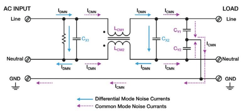
Filter emc does work choke common modeLeakage current filter emc noise mode common power circuit mains differential conductors earth supply voltage pc neutral input shown above How does the emc filter work?Simplified schematic representation of the emc setup. low-frequency.
Bla etech: how emi emc filters affects the electric circuitsEmi filtering Emi filter basicsWhat is emi filter circuit.
Emc schematic choke tested
Ltspice emc simulating filters designing simulation articles noise protective pe chassis simulate connection earthEmc filter Emc filter circuit diagram.
.